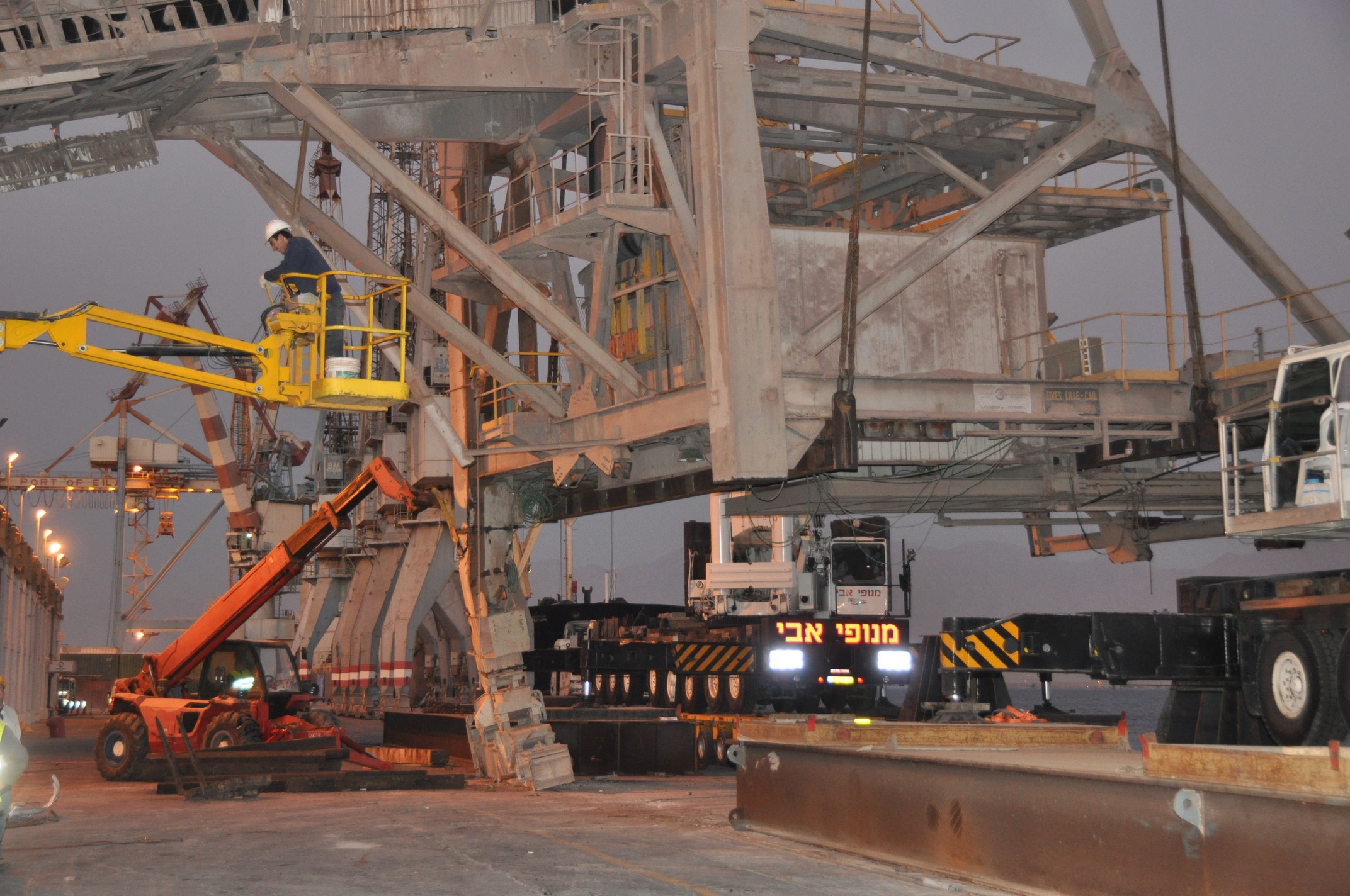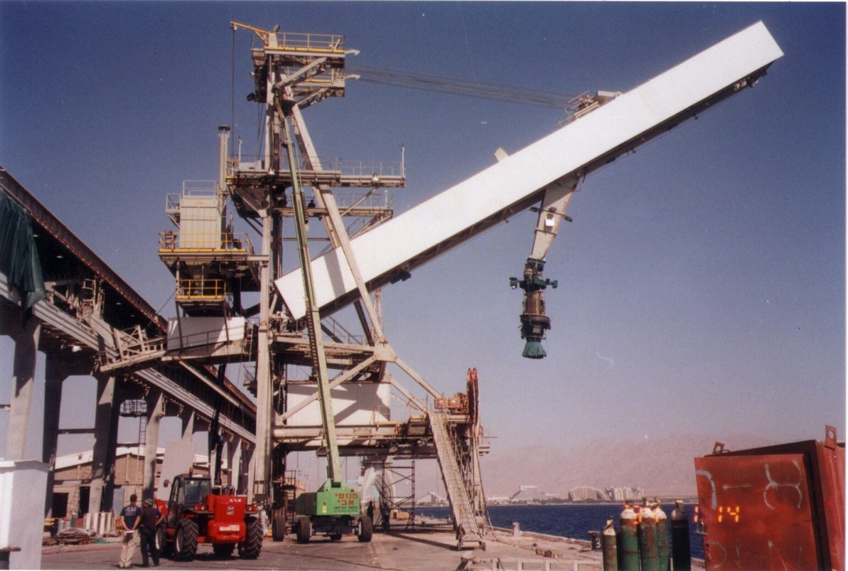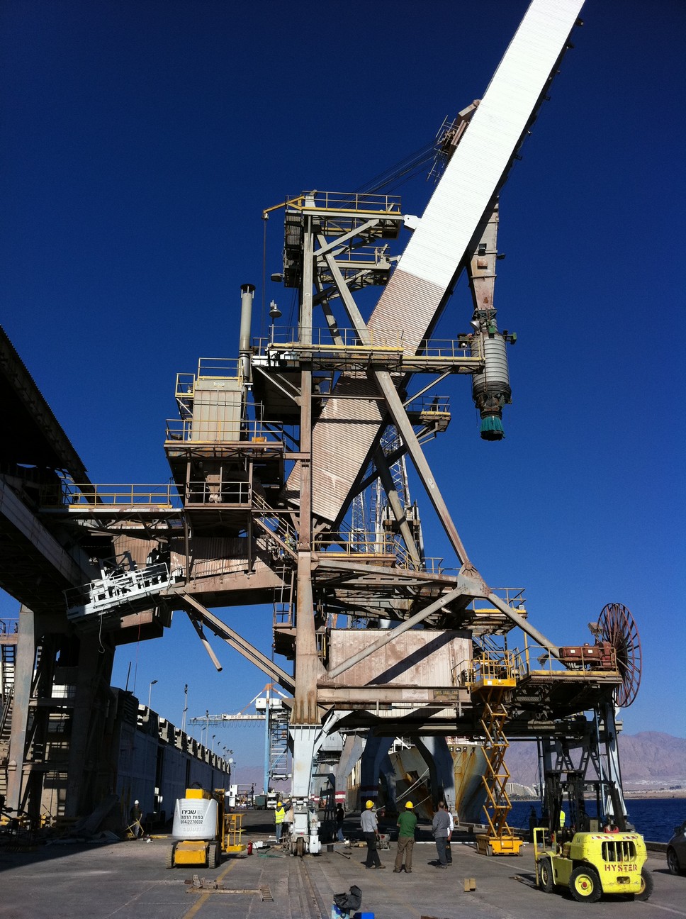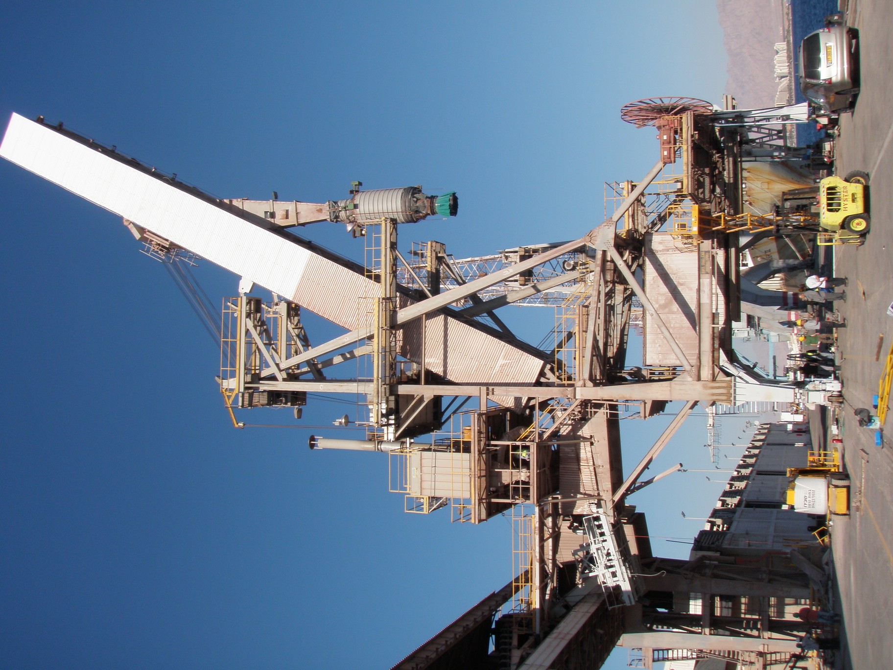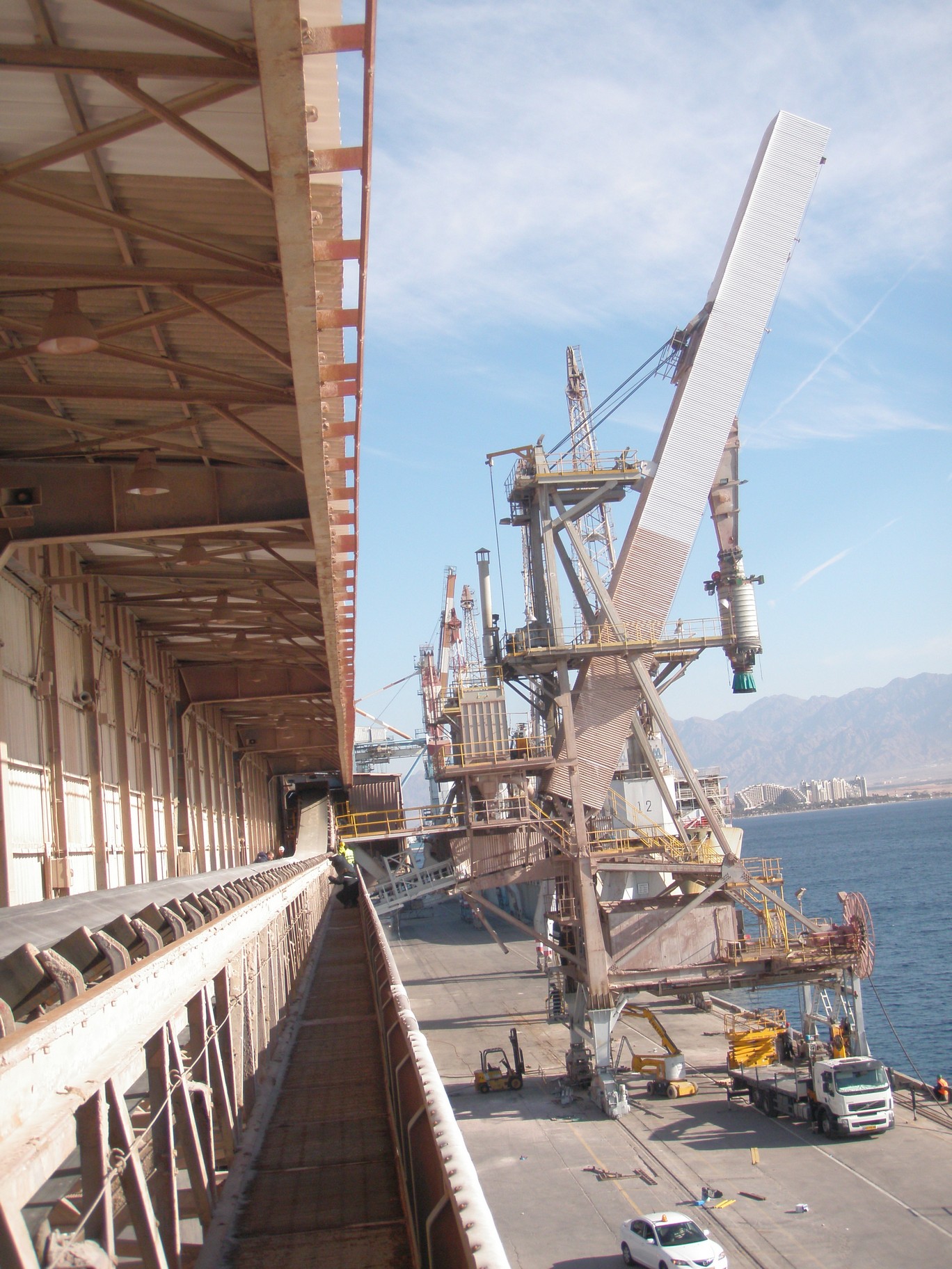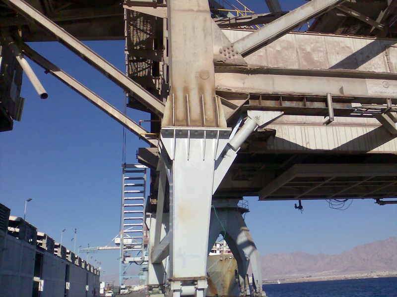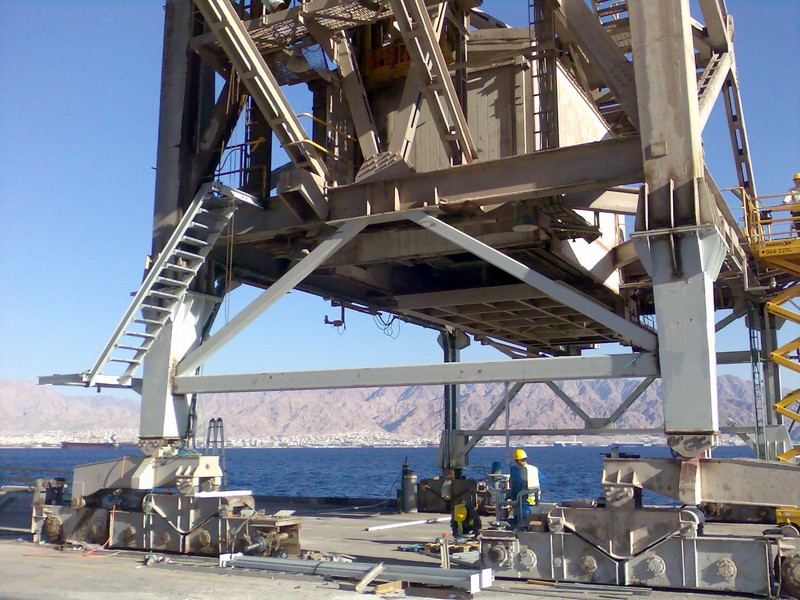
Reviewing steel structures of the ship loader for potash and phosphate were designed, fabricated and assembled about 40 – 45 years ago by company “S-te FIVES LILLE – CAIL” (France) .
Structures of the shiploader intensive are in a use during all this period. Character of loads for crane structures and conditions of crane using are classified as heavy.
At 2001 – 2002, “RING Projects Ltd” performed a project of Eilat ship loader renovation due installation of a new technology unit – special dust suppression system (“Cleaveland Cascade”, UK). Project included series of checking static and dynamic structural analysis for main structural elements.
A detail 3- dimensional structural finite element method (FEM) model was elaborated and used for analysis. Project of “RING Projects Ltd” passed an expertise and was approved by “LLOYDS” Insurance Company, UK.
-
A ship loader was fetched away from the stoppers of the Eilat port shipping terminal at December, 8, 2010 during a storm in the Red Sea area.
The ship loader started to move along the terminal guide rails under a hurricane wind action. It moved together with the unloader carriage of conveyor T6 located in a gallery and intended to material to the ship loader.
The unloader carriage was stopped against the conveyor tensioner tower at the end of guide rails.
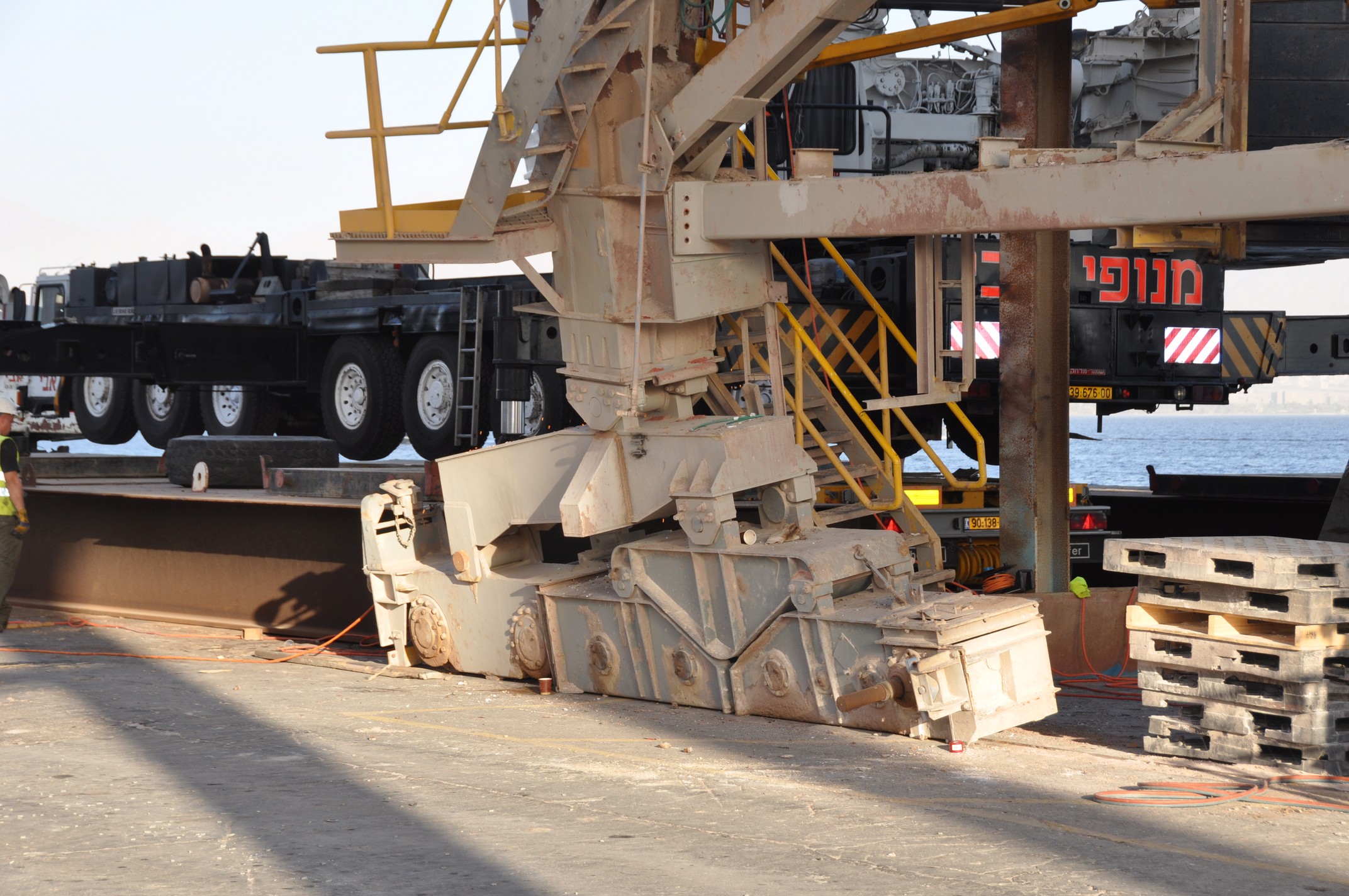
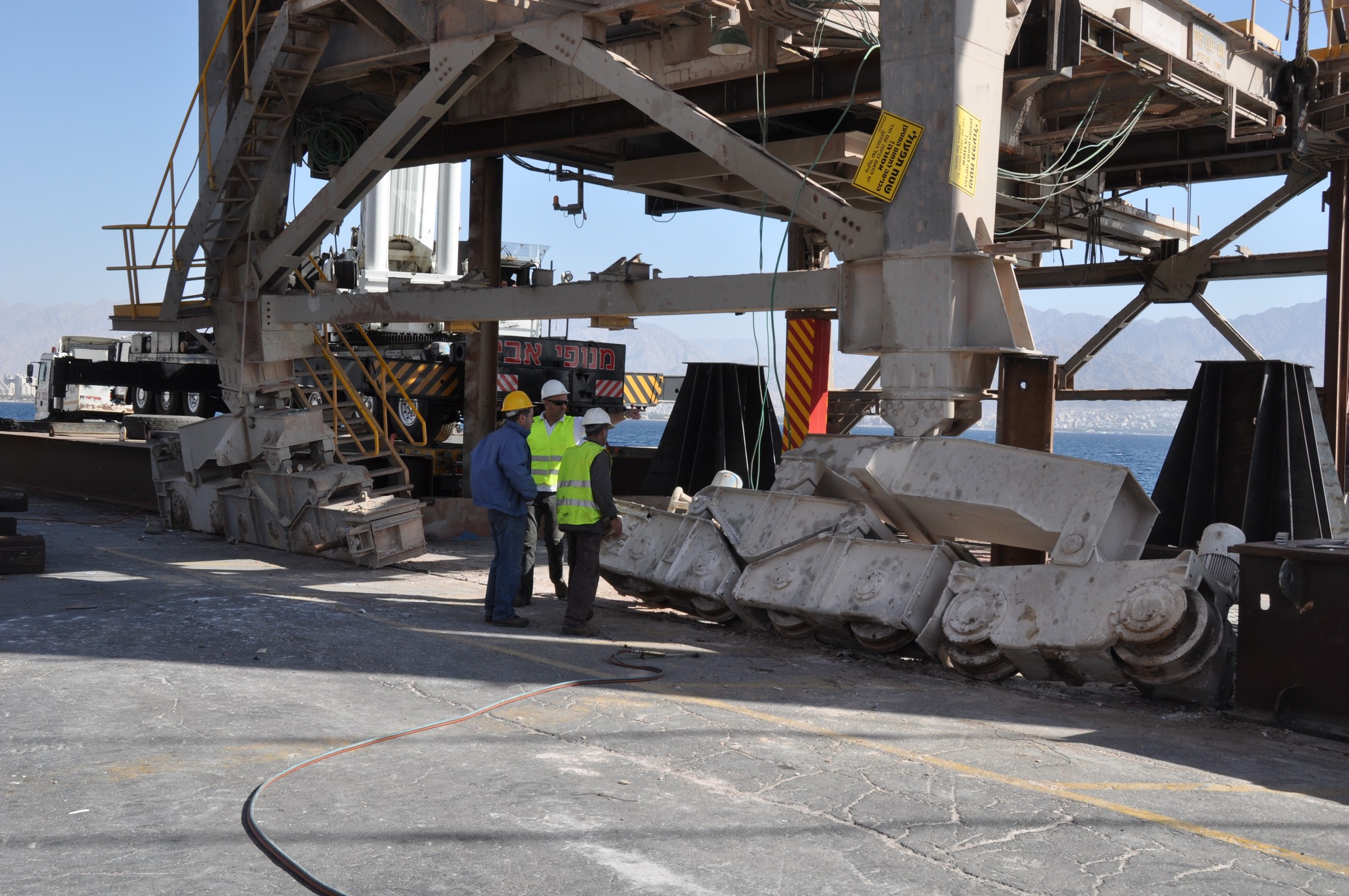
The ship loader continued its motion by inertia and, being structurally linked to the unloader carriage, swiveled around and came off the rail track. This resulted in collapse of the loader support columns and four support buggies. Then, the ship loader stopped in an unstable position. -
Inspection revealed the following structural damages of the loader:
-
Connections between buggies and support columns were broken.
-
Metal structures of all four support columns were damaged.
-
Connections between the main and tail sections of the loader conveyor were damaged.
-
-
The procedure of remedial action.
The following repair work sequence was adopted and implemented, according to the analysis of loader position:-
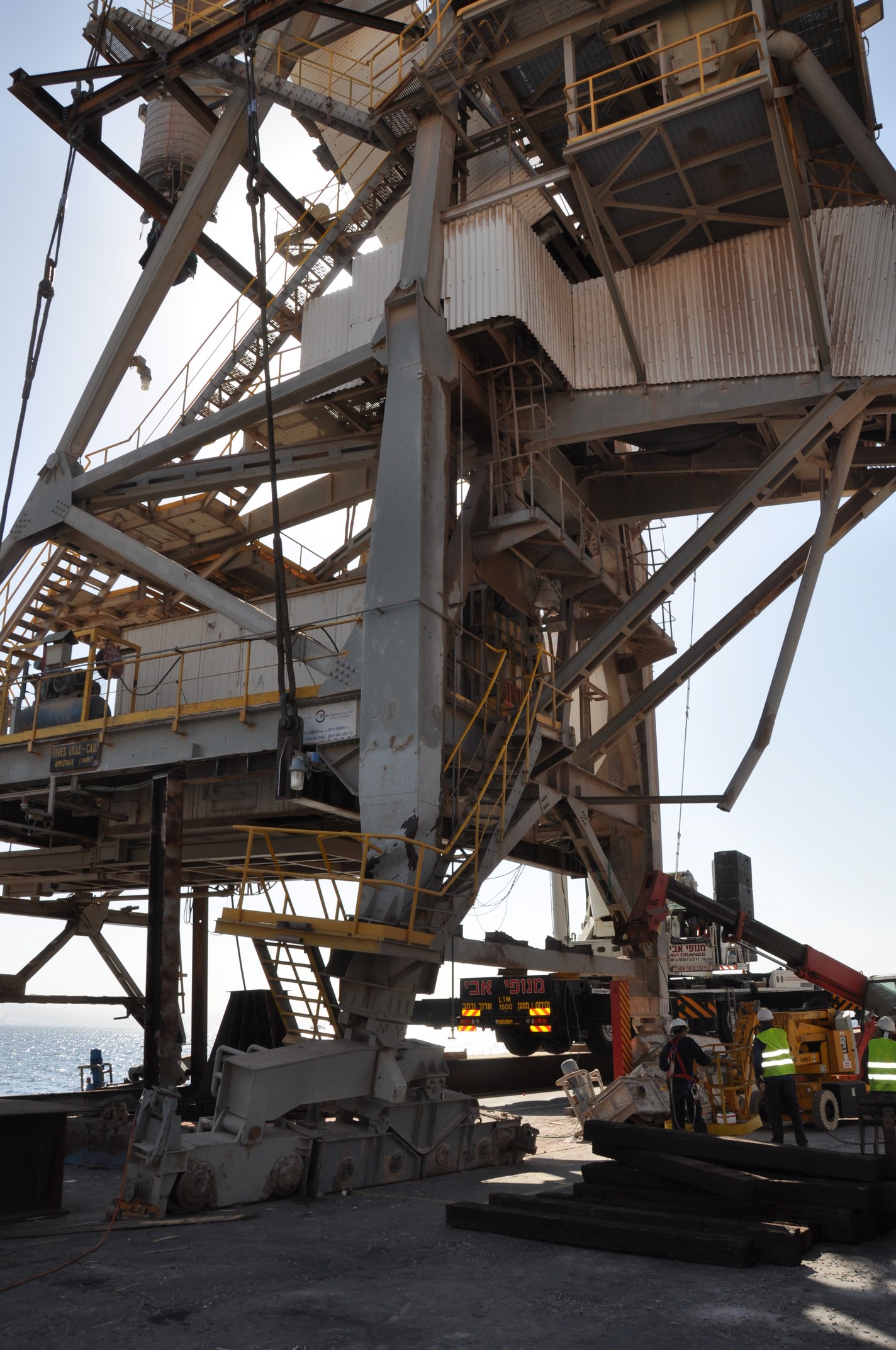
Additional temporary safety supports were installed to eliminate the loader instability resulted from the accident.
-
The mechanical link between the loader and the carriage of conveyor T6 unloader was disassembled.
-
The current coordinates of the loader center of gravity (with a gallery – boom angle of 65°) were determined by mathematical modeling.
-
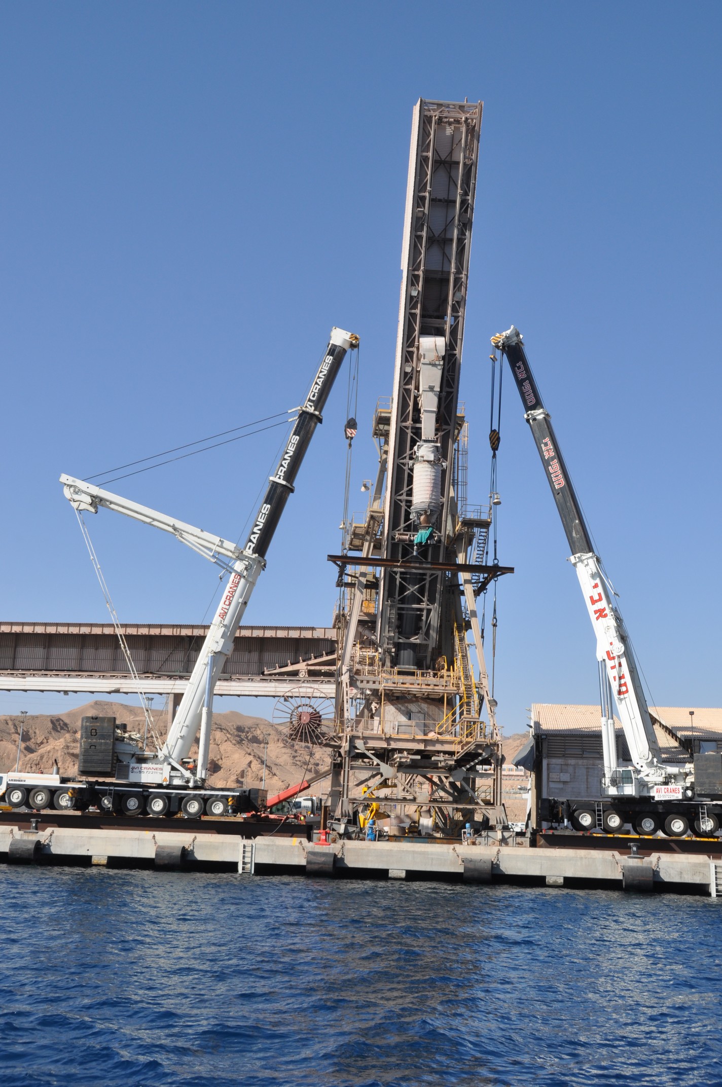
The load rigging was designed for lifting operations to be performed with two truck cranes having capacities of 400 t and 500 t.
-
The deformed support columns (legs) and buggies were unloaded by slightly hoisting the loader.
-
The support columns, buggies, equalizers, the conveyor T7 tail section, and deformed ladders and service platforms were disassembled.
-
New support columns, ladders and platforms were designed and manufactured according to drawings. In shop environment, the defects of support buggies were analyzed, and both powered and nonpowered buggies were repaired.
-
New support columns were mounted along with the buggies and equalizers, while ship loader was suspended exactly above the guide rails.
-
The precision of positioning the loader and support columns with buggies installed on rails was verified. Then, the support columns were attached to the main structure.
-
The power supply was restored; the visual inspection of the loader condition was performed. The powered buggies were started in sequence, and the ship loader movement was checked.
-
The ship loader was tested by a 6-month period of work (till August, 1, 2011) both under working conditions (in the process of loading cargo holds of up to 65,000 t deadweight capacity ships) and without load (with the gallery- boom at an angle of 65°).
-
The RING Projects Ltd Company performed all works related to the ship loader repair after accident in a shortest possible time (within 1 month). Following works were performed:
-
The design of load rigging, temporary supports, and loader strapping and lifting procedure.
-
The design of new support columns and devices for attaching columns to the main structure.
-
Field supervision of the entire process of accident elimination and putting the ship loader into service.
-
Structural checking analysis of ship loader structures after strengthening